DSP-DVR-M Digital 3 Phase Voltage Relay/Display meter seperated from Converter
Digital 3 Phase Voltage Relay/Display meter seperated from Converter

Main Feature
- MCU based control, 8 Pin Type Compact size
- Easy Installation
- Panel Flush Mounting Type
- DSP-DVR-M :5 digit window
- Operation based on direct line voltage detection
- Protection : Over/Under voltage, Phase Loss, Reverse Phase, Voltage Unbalance
- Indication : Voltage[Line/Average], Frequency
- Time-Voltage operational characteristic → Definite / Inverse
- Over/Under Voltage Protection
- Rated Line Voltage → 100 ~ 500VAC
- Over Voltage protection Range → within (+) 20% to line voltage
- Under Voltage protection Range → above (–) 20% to line voltage
- Possible to preset operation time for over/under voltage each, repectively
- Perfect check for initial line state
- ”dt”(trip delay time) mode is preset “OFF”
- Preset “a” in “out” mode
- Main trip output(95-98) is energized (Open → Close ) in case the rated line voltage with normal forward phase state is sensed initially
- Main trip output(95-98) is trip(Close → Open) within 0.5sec after energizing(Open→Close) if the initial state is under phase loss
- Main trip output(95-98) is trip(Close → Open) after operational preset time is elapsed from instant energizing point(Open→Close) as showing a trip cause if the initial line state is under over/under voltage,reverse phase, voltage unbalance
- v.OFF is shown in case the line voltage is not sensed initially or voltage is dropped to zero(0) while the normal operation is doing
- Preset “a” in “out” mode
- Preset “b” in “out” mode
- Main trip output(95-98) is not energized (Open → Open ) even if the rated line voltage with normal forward phase state is sensed initially
- Main trip output(95-98) is trip(Open → Close) within 0.5sec if the initial state is under phase loss
- Main trip output(95-98) is trip(Open →Close) after operational preset time is elapsed as showing a trip cause if the initial line state is under over/under voltage,reverse phase, voltage unbalance
- v.OFF is shown in case the line voltage is not sensed initially or voltage is dropped to zero(0)
- ”dt”(trip delay time) mode is preset a value(time)
- Preset “a” in “out” mode
- Main trip output(95-98) is energized (Open → Close ) after “dt” is elapsed in case the rated line voltage with normal forward phase state is sensed initially
- Main trip output(95-98) is still opened(not trip) even after “dt” is elapsed if the initial state is under phase loss,also “PL’is shown
- Main trip output(95-98) is energized (Open → Close) right after “dt” is elapsed if the initial line state is under over/under voltage, voltage unbalance, and then it is trip(Close → Open) after operational preset time is elapsed from energizing point(Open→Close) as showing a trip cause
- v.OFF is shown in case the line voltage is not sensed initially or voltage is dropped to zero(0) while the normal operation is doing.
- ”rP” is shown as main trip output(97-98) is still opened(not trip) after operational trip time (0.5sec) without concerning with “dt” if reverse state is sensed initially
- Preset “a” in “out” mode
- Preset “b” in “out” mode
- Main trip output(95-98) is not energized (Open → Open ) in any case
- Main trip output(95-98) is trip (Open → Close) after “dt” is elapsed if the initial state is under phase loss as “PL’is shown
- Main trip output(95-98) is trip (Open → Close) right after “dt”is elapsed as showing a trip cause if the initial line state is under over/under voltage, voltage unbalance
- v.OFF is shown in case the line voltage is not sensed initially or voltage is dropped to zero(0)
- ”rP” is shown as main trip output(97-98) is still closed(not trip) after operational trip time(0.5sec) without concerning with “dt” if reverse state is sensed initially
- ”dt”(trip delay time) mode is preset “OFF”
- 3 phase line voltage/average voltage and /or frequency is shown ordery in every 3sec
- Stored the information for latest 8 trip event
- Reset after a trip : auto or manual
- Self-diagnostics to check if this relay is ready to work or not
Technical Specification
- Time preset
- Protection delay time(dt):1~60 sec/definite
- Over voltage trip delay time(ovt)
- 0.2~20 sec/definite
- 1~10 Class/inverse
- Allowable tolerance
- Voltage:±3%
- Time
- t<=2sec:± 0.2sec, t>2sec:±10%
- Reverse phase:+10%
- Control power
- AC 85V∼AC260V,50/60Hz (DC90V∼DC370V)
- DC24V(Optional)
- Trip output relay:95-96-98/1c(1-SPDT),5A/Resistive
- Application environment
- Temperature
- Operation:-25 degree C∼+70degree C
- Storage :-40 degree C∼+80 degree C
- Temperature
- Insulation Resistence/IEC-60255-5:Case–Circuit: 10Mohm/500VDC
- High Voltage Withstand Test/IEC-60255-5:*Case–Circuit:AC2000V,60Hz,1 min *Contact-Contact:AC 1000V,60Hz,1 min
- Lightning Impulse Voltage Withstand Test/ IEC-60255-5:*Circuit-Ground,Circuit-Circuit: 1.2/50(uS),5KV *Control Circuits:1.2/50(uS), 5KV
- 1 MHz Burst Immunity Test:IEC 61000- 4-18:2.5KV,Positive/Negative under 2sec
- Electrostatic Discharge:IEC-61000-4-2:Air :Level 3, 8KV, Contact:Level 3, 6KV
- Radiated Electromagnetic Field Disturbance:IEC-61000-4-3:Level 3, 10V/m
- Electric Fast Transient Burst :IEC-61000-4-4:Power,trip output:Level 4,4KV
- Surge Immunity test:IEC-61000-4-5:trip output :1.2X50uS,2KV(0O,90, 180 , 270)
- Conducted Disturbence Test:IEC-61000-4-6:10V, Level 3
- Consuming power:4W Max
Cad
- CATEGORY
- SUBJECT
- DOWNLOAD
- MODIFY DATE
- DWG
- DSP-DVR, DVR-M 치수도 결선도
- DSP-DVR, DVR-M.dwg
- 2021-02-09
Certification
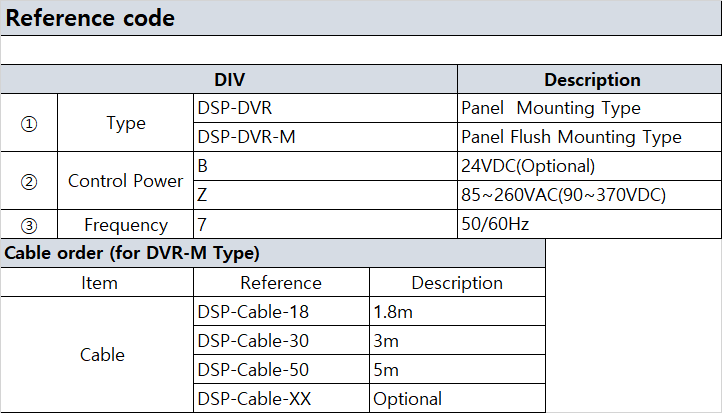
Ordercode