DSP-IRM Power Line Insulation Resistance Measurement Relay/Panel Flush Mounting Type
Power Line Insulation Resistance Measurement Relay/Panel Flush Mounting Type

Main Feature
- Panel Flush Mounting Type
- Access restricted to authorized operator : Password
- Mini compact size, convenient installation with 8pin socket → very useful to have a maintenance for aged motor control panel
- Measurement ,Indication and Alarm for power line insulation resistance through 500VDC directly
- The followed condition for the safety shall be satisfied to measure
- Input P1-P2 must be closed state through Aux “b” output of MC(Magnetic Contactor) to control a motor and/or “b” output of MCCB to prove power-off state of motor
- Earth terminal “E” and 500VDC output terminal “L” connected with “b” aux output of MC must be composed with closed circuit → refer application sequence diagram
- Indication for measured insulation resistance during motor stop state
- the latest measured value is shown
- the output for alarm comes out if the measured value is lower than preset
- the confirmation for stored measurement value
- the measured value and the stored order is shown alternatively
- the latest among 8 stored measured value is shown firstly as turned on #1 LED
- Indication for measured insulation resistance during motor run state
- OPEN” LED is turned on
- the latest measured value is indicated
- Preset mode concerned with insulation resistance measurement :IrAL,rEcd,rEnb,Auo,cLas,1st
- Indication for measured value
- the latest is shown while the measured action is not executed and is able to check the rest of 8 stored value as controlling “UP” and “DN” key,but “nonE” is shown if there is stored no more
- “IrPS” is shown over 3500MOhm which means “very good”
- measured value under 50KOhm is assumed Zero
- “Ir-0” is flickered if measured value is 0(zero)
- Safety condition to measure insulation resistance
- Critical condition: Input P1-P2 must be closed state through Aux “b” output of MC(magnetic Contactor) to control a motor
- “oPEn” LED is turned on if it is open state and the measurement is not possible
- Operator needs to check wiring state.
- Critical condition: Input P1-P2 must be closed state through Aux “b” output of MC(magnetic Contactor) to control a motor
- Additionally.“b” output of MCCB to confirm power-off for motor shall be connected with serial connection to MC if possible
- 500VDC output terminal “L” connected with “b” aux output of MC and earth terminal “E” must be composed with closed circuit → refer application sequence diagram
- Optional choice: to make motor not to start as making serial connection with output of R1-R2 to MC coil→ in this case, it is recommend to use external aux relay
- Self-diagonostic : output of R1-R2 is energized as pressing "CLR" key for 3sec → reset is done as pressing “CLR” key once more
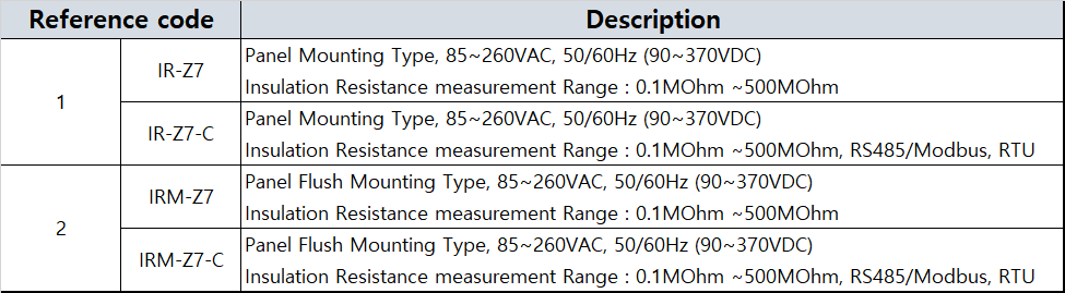
- It is possible to send the latest measured value through RS485 communication
Technical Specification
- Control Power
- 100VAC~240VAC, 50/60Hz(90VDC~ 370VDC)
- 24VAC/DC(Optional)
Insulation Resistance measurement Range : 0.1MOhm ∼500MOhm
- Tolerable Rate
- R≤1M : ±0.05M
- 1M<R≤50M : ±5%(avg)
- 50M<R≤200M : ±10%(avg)
- 200M<R<500M : available range
- Alarm/Measurement output :R1-R2/1a(1-SPST), 3A/Resistive
- Application Environment
- operation : -25℃ ~ +70℃
- Storage : -40℃ ~ +80℃
- Humidity : 30 ~ 85%, non-condensing
- Insulation Resistence/IEC-60255-5 : circuit-case, 100Mohm 이상, 500VDC
- high Voltage Withstand Test/IEC-60255-5
- circuit-case : AC 2000V, 60Hz, 1 min
- contact-contact : AC 1000V, 60Hz, 1min
- Lightning Impulse Voltage Withstand Test)/IEC-60255-5
- Circuit-Ground, Circuit-Circuit : 1.2/50 uS, 5KV
- Control Circuits : 1.2/50uS, 3KV
- 1 MHz MHz Burst Immunity Test/IEC 60255-22-1:2.5KV, Positive/Negative under 2sec
- Electrostatic Discharge /IEC-60255-22-2
- Air : Level 3, 8KV
- Contact : Level 3, 6KV
- Radiated Electromagnetic Field Disturbance/IEC-60255-22-3 : Level 3, 10V/m
- Electric Fast Transient Burst/IEC-60255-22-4 : Power relay output /Power source, Level 4, 4KV
- Surge Immunity test/IEC-60255-22-5 :Relay output :1.2X50uS,2KV((0°, 90°, 180°, 270°)
- Conducted Disturbence Test/IEC-60255-22-6: 10V, Level 3
- Digital Communication
- Physical : 2 wire RS 485
- Address : 1 ~ 250
- Speed : 9.6/19.2/38.4/57.6/76.8/115.2kbps
- Connection : Input/Output : Screw Terminal
- Termination resistance : it needs to use external resistance with 120 Ω
- Cable : Sheathed 2 Pair
- Power Consumption : 4W max
Cad
- CATEGORY
- SUBJECT
- DOWNLOAD
- MODIFY DATE
- DWG
- DSP-IR,IRM
- DSP-IR,IRM.dwg
- 2020-11-17
- DSP-IR,IRM
- DSP-IR,IRM.pdf
- 2020-11-17
Certification
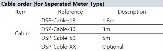
Ordercode